Compact installation
Wafer layout for projects with limited installation space.

JACKETED WAFER RANGE
A compact wafer ball valve with a jacketed body and pneumatic actuation. Confirm the valve and jacket requirements for the application.
Prepare a product enquiry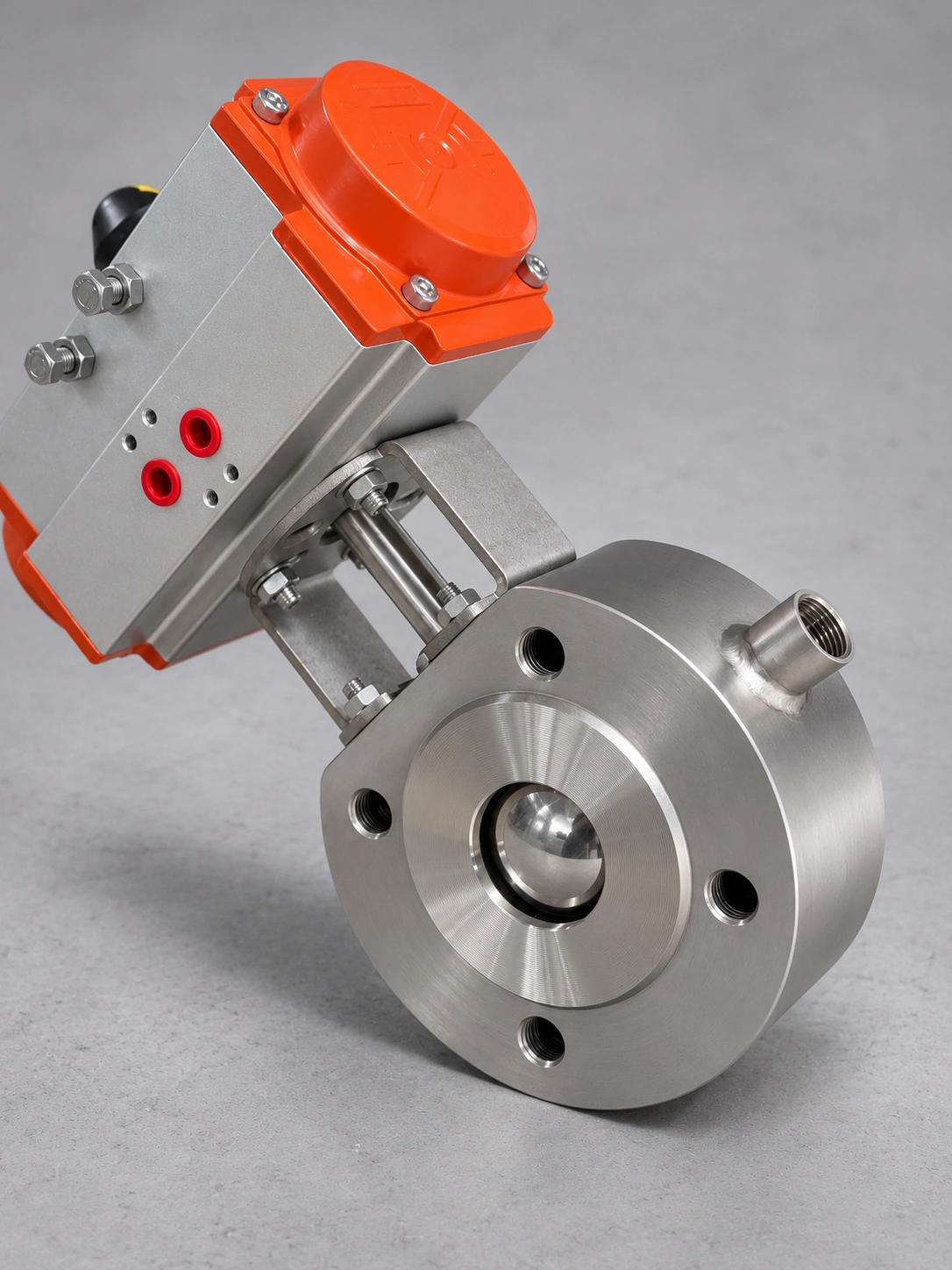
The pictured configuration combines a compact wafer valve, jacket connections and a pneumatic actuator. Final dimensions, materials and operating limits are confirmed for the specific model and order.
PRODUCT DESCRIPTION
A jacketed body adds a separate jacket circuit around the compact valve body. Specify the process and jacket conditions together when selecting the valve.
Wafer layout for projects with limited installation space.
Confirm the jacket medium, connection size and operating conditions with the enquiry.
Valve requirements and actuator configuration are reviewed together for the application.
Dimensions, materials and pressure ratings are confirmed for the selected configuration.
Please provide valve size, process medium, pressure and temperature, connection standard, jacket medium and pressure, and actuator requirements.
For product selection, specify the required DIN/EN, ANSI/ASME or JIS standard. Connection dimensions, pressure ratings and conformity requirements are confirmed for the specific model and order.
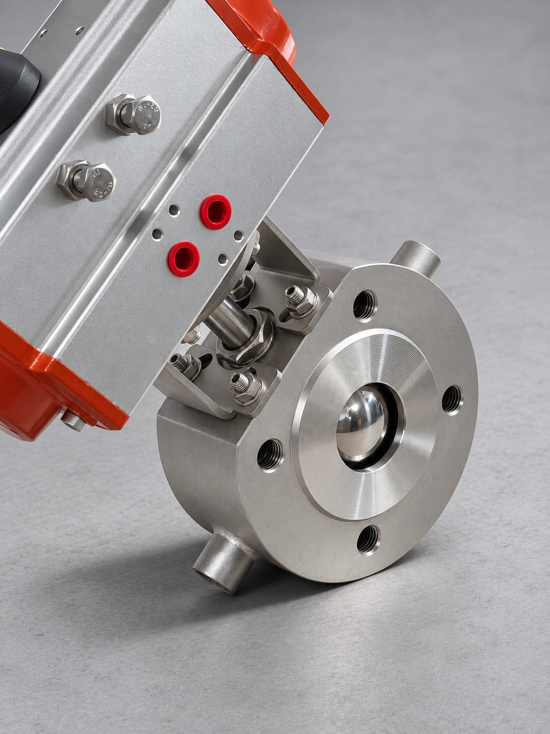
保温薄型球阀
BQ73/74F (PPL, M)-16
Dimensions & materials
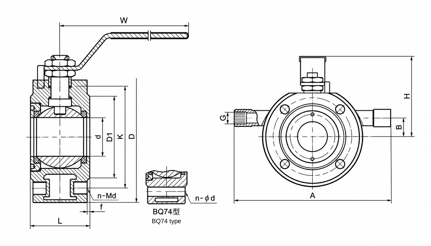
BQ73/74F-16 · Unit: mm
Swipe the table to view all dimensions on smaller screens.
| DN (mm) | DN (in) | d | G | A | B | L | D | K | D1 | BQ73 n-Md | BQ74 n-φd | f | H | W |
|---|---|---|---|---|---|---|---|---|---|---|---|---|---|---|
| 15 | 1/2" | 14 | G1/2" | 150 | 15 | 35 | 90 | 65 | 46 | 4-M12 | 4-φ14 | 2 | 65 | 145 |
| 20 | 3/4" | 19 | G1/2" | 160 | 20 | 38 | 100 | 75 | 56 | 4-M12 | 4-φ14 | 2 | 68 | 145 |
| 25 | 1" | 25 | G1/2" | 190 | 20 | 42 | 110 | 85 | 65 | 4-M12 | 4-φ14 | 2 | 85 | 180 |
| 32 | 1 1/4" | 29 | G1/2" | 210 | 25 | 50 | 135 | 100 | 76 | 4-M16 | 4-φ14 | 2 | 90 | 180 |
| 40 | 1 1/2" | 38 | G1/2" | 230 | 30 | 60 | 145 | 110 | 84 | 4-M16 | 4-φ18 | 2 | 120 | 220 |
| 50 | 2" | 48 | G1/2" | 250 | 30 | 70 | 160 | 125 | 99 | 4-M16 | 4-φ18 | 3 | 130 | 230 |
| 65 | 2 1/2" | 64 | G1/2" | 270 | 45 | 95 | 180 | 145 | 118 | 4-M16 | — | 3 | 140 | 250 |
| 80 | 3" | 76 | G1/2" | 300 | 50 | 118 | 195 | 160 | 132 | 8-M16 | — | 3 | 145 | 290 |
| 100 | 4" | 95 | G1" | 340 | 70 | 140 | 215 | 180 | 156 | 8-M16 | — | 3 | 200 | 350 |
| 125s | 5" | 100 | G1" | 360 | 80 | 175 | 245 | 210 | 184 | 8-M16 | — | 3 | 215 | 460 |
| 150s | 6" | 125 | G1" | 420 | 95 | 210 | 280 | 240 | 211 | 8-M20 | — | 3 | 270 | 610 |
| 200s | 8" | 150 | G1" | 460 | 120 | 280 | 335 | 295 | 266 | 12-M20 | — | 3 | 330 | 840 |
Face-to-face reference: Q/OLF001-88.
BQ73: threaded flange holes. BQ74: plain flange holes (DN15-50 listed).
s suffix and blank BQ74 entries are retained from the supplied sheet; blank entries are shown as —.
Material designations follow the supplied sheet. The drawing shows a manual valve; overall dimensions of the pictured pneumatic assembly are confirmed separately.
| Part | BQ73/74-16C | BQ73/74-16P | BQ73/74-16R |
|---|---|---|---|
| Valve body | A105 | Z1Cr18Ni9Ti or 304 | Z1Cr18Ni12Mo2Ti or 316 |
| Ball | 1Cr18Ni9Ti or 304 | 1Cr18Ni9Ti or 304 | 1Cr18Ni12Mo2Ti or 316 |
| Jacket | 35 | 1Cr18Ni9Ti or 304 | 1Cr18Ni9Ti or 304 |
| Valve stem | 1Cr18Ni9Ti or 304 | 1Cr18Ni9Ti or 304 | 1Cr18Ni12Mo2Ti or 316 |
| Valve cover | 35 | Z1Cr18Ni9Ti or 304 | Z1Cr18Ni12Mo2Ti or 316 |
| Seal seat | F: Reinforced PTFE or PTFE · PPL: Para-polyphenyl · M: High-strength graphite | ||
| Packing | Reinforced PTFE or PTFE · Para-polyphenyl · Flexible graphite | ||